Niknejad, "A Robust 24-mW, 60-GHz Receiver in 90-nm Standard CMOS", ISSCC 2008, Session 9, pp 6-8. Razavi, "A Millimeter-Wave CMOS Heterodyne Receiver With On-Chip LO and Divider", IEEE J. Razavi, "A 60-GHz CMOS Receiver Front-End", IEEE J. Long, "SiGe Radio Frequency ICs for Low-Power Portable Communications", in Proceedings of the IEEE, Vol. Cripps, RF Power Amplifiers for Wireless Communications, 1st edition, Artech House, Massachusetts, pp 12-14. Gonzalez, Microwave Transistor Amplifiers: Analysis and Design, 2nd edition, Prentice Hall, NY, 1997, p.

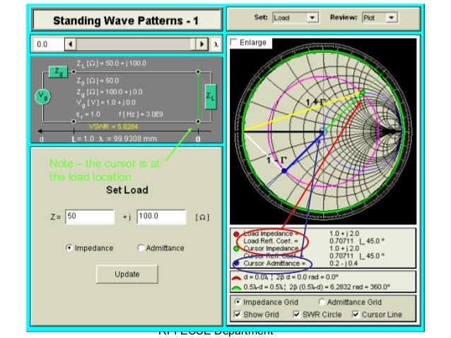
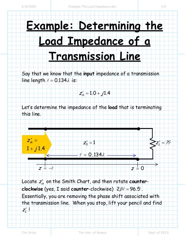
In any case, in dealing with transmission lines the designer could also greatly benefit from the use of assisting tools such as EM software, Mathcad/MATLAB routines, and transmission-line tools, both to speed up the design and to get a better understanding of the circuit at hand. In fact, transmission lines can be designed inside a silicon IC at these frequencies, and some people have done just that. At these frequencies, long IC metal traces need to be regarded as transmission lines. In recent years, the possibility of designing CMOS circuits that operate at millimeter-wave frequencies - 30 GHz and above - has been explored. Propagation delays are usually dominated by components'' parasitics. One of the advantages of the tiny dimensions of ICs is that transmission-line effects can be neglected in many cases. This article covers the mathematics behind creating the chart and its physical interpretation. Traditionally, transmission lines have been implemented exclusively on PCBs. Smith Charts are an extremely useful tool for engineers and designers concerned with RF circuits.

The use of the Smith Chart or a Mathcad/MATLAB routine can not only make the procedure less burdensome but also help the designer visualize things better as the circuit is fine-tuned.nnImpedance matching networks can be designed using lumped inductors and capacitors or transmission lines. As a result, optimizing a matching network in order to meet all the design specifications requires multiple iterations, which can become very laborious and tedious even with the aid of a circuit simulator. In any case, maximizing the power delivered to the load is just one aspect of the design of an RF circuit. Others include noise performance, stability, and linearity. In any case, maximum power transfer is just one aspect of the design of an RF circuit. For power amplifiers, a matching network transforms the load impedance into Vmax/Imax, the ratio of the maximum rated voltage of the active device divided by the maximum current it can deliver. For small-signal RF circuits, the power delivered to the load is maximized by conjugate-matching it to the source with a matching network.


\): Moving along the ℜ Y s Y 0 = 1 Y s Y 0 1 circle with a stub.A matching network optimizes the transfer of power from a source to a load by maximizing the power delivered to the load while meeting other performance specifications.


 0 kommentar(er)
